The above graphic shows the basic Young's slits experiment. Considering the light as a wave, it is not difficult to see how interference occurs. Each slit acts like a new source of waves. The waves spread out (diffract) from each slit and begin to overlap. Like water waves, where a wave crest from one source coincides with a crest from the other source, they reinforce each other. The amplitude of the wave at that point is then doubled. Where a crest coincides with a trough, they cancel each other out resulting in zero amplitude (flat) at that point. Because the waves emanating from the two slits were originally from the same source, they always keep in step with each other. At the screen this results in bands of light where reinforcement is occurring and dark where cancellation is occurring. These bands or 'fringes' are called a diffraction pattern. The distance between the fringes y = λD/a where λ (pronounced lambda) is the wavelength of the light, D is the distance from the slits to the screen and 'a' is the distance between the slits. All lengths must be in the same units (usually meters).
To produce fringes that are visible to the unaided eye, the distance between the slits needs to be very small. For example, consider green light with a wavelength of 520nm (0.000, 000, 52 meters). If the fringes are to be 1mm apart and the distance from the slit mask to the screen is 1m, then a = λD/y = (520x10-9 x 1) / 0.001 = 520x10-6. This means that the slits would need to be 0.52mm apart.
The Relationship Between Object and Diffraction Pattern.
The way in which information about an object is transferred by light (or any electromagnetic wave) is rather interesting. The diffraction pattern of an aperture mask (or any object) is not just a meaningless pattern. It contains a description of the object. Proof of this is that an ordinary lens can be used to convert the diffraction pattern back into an image of the object. This is how the human eye works. The light arriving at your eyes is a diffraction pattern of the objects that you are looking at. Your eyes convert the diffraction pattern back into an image on the retina.
It is not normally possible to see how information describing an object is encoded in the diffraction pattern. The reason for this is that most objects have a complicated shape and light is normally composed of a range of wavelengths. To see what is happening it is necessary to simplify things. The simplest light source in this context is a coherent monochromatic (single wavelength) source such as a laser. The simplest object is a sinusoidal diffraction grating.
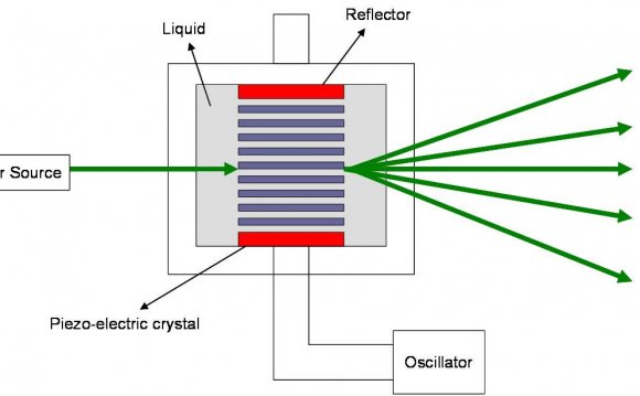
A sinusoidal diffraction grating is like a very fine venetian blind. However, rather than alternating abruptly between clear and opaque, the light transmission of a sinusoidal grating varies smoothly in a sinusoidal profile. When a monochromatic light beam is passed through a sinusoidal grating, it is split into three beams. One beam goes straight through and the other two are at equal angles to the straight through beam.
In the photograph above, a 405nm laser beam is passing through a tank of water dosed with fluorescein dye. The laser light has a short enough wavelength to make the dye fluoresce. The laser is on the left, outside the tank. In the left hand end of the tank, immersed in the water, is a sinusoidal diffraction grating. The grating has 1000 lines per mm. The 'straight through' beam and the two symmetrical side beams can be clearly seen. The laser, the dye and the diffraction grating were obtained on eBay.
The number of lines per mm of the grating is called the frequency of the grating, or more specifically the spacial frequency. If the frequency of the grating were increased, the angle between the beams would increase in proportion (for small angles). In other words, the angle between the beams is proportional to the spacial frequency of the grating. The relationship is d Sin θ = λ where d is the period of the grating, θ is the angle of the beam from the normal and λ is the wavelength of the light.
If the diffraction grating had more spacial frequency components, a pair of beams would be generated for each of them. This ability to split a pattern into its individual sinusoidal components is called a Fourier transform. A diffraction pattern is therefore the optical Fourier transform of the object.
RELATED VIDEO


RELATED FACTS
-
 Optics is the branch of physics which involves the behavior and properties of light, including its interactions with matter and the construction of instruments that use or detect it. Optics usually describes the behavior of visible, ultraviolet, and infrared light...
- The Smith–Purcell effect was the precursor of the free electron laser (FEL). It was studied by Steve Smith, a graduate student under the guidance of Edward Purcell. In their experiment, they sent an energetic beam of electrons very closely parallel to the surface of...
-
 The theoretical and experimental justification for the Schrödinger equation motivates the discovery of the Schrödinger equation, the equation that describes the dynamics of nonrelativistic particles. The motivation uses photons, which are relativistic particles with...
Share this Post
latest post
-
 Holographic Presentation March 30, 2025
 -
 Museum of Holography New York March 20, 2025
 -
 Holographic Bookmarks March 10, 2025
 -
 DIY hologram February 27, 2025
 -
 Equation for diffraction grating February 17, 2025
 -
 Halloween hologram projector February 7, 2025
 -
 Hologram meaning January 28, 2025
 -
 UK Fake driving licence with hologram January 18, 2025